NC-Monitor 2.0 Software Package
Software package for archiving and visualization of any technical and technological parameters, such as general vibration level, mechanical parameters, temperature, pressure
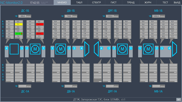
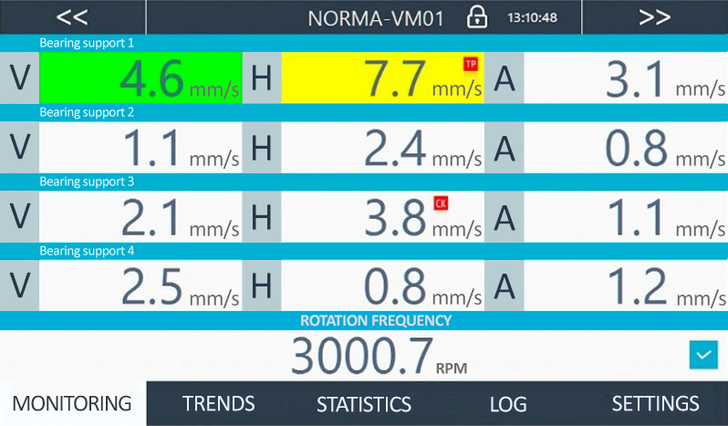
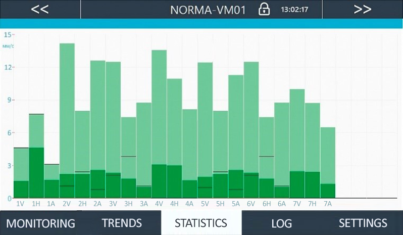
- Several types of display of current parameter values (mimic diagram, table, histograms);
- Color indication of alarming parameter values, markers of inactive events;
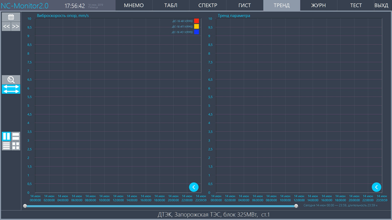
- Customizable screen for presenting archived data for a selected period of time;
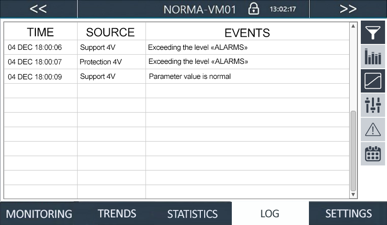
- Filtering log events;
- Reporting by parameters and events;
- Setting settings individually for each parameter or for groups of parameters;
- Express test mode for equipment and communication lines.
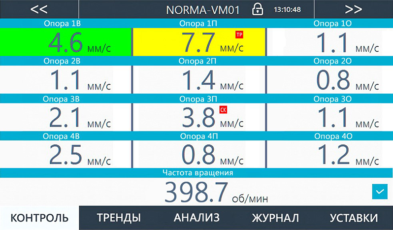
For a local workstation with a 7’’ monitor, the version of the NС-Monitor 1.0 software package is used. This version retains all the functionality of the NC-Monitor 2.0 package (except for the mimic diagram) with adaptation for the touch mini-monitor.
Monitoring smoke exhausters and blower fans
COMPOSITION OF THE SYSTEM
The system is equipped with measuring channels for vibration of supports NCD0110R2 and the channel of rotation frequency and phase synchronization NCD0411. To configure the system, view and analyze the archived data, the software package NORMA-VM SW1.0 Exh&Fun.
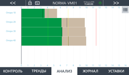
Meets the requirements of ISO 10816-3:2009
FUNCTIONALITY
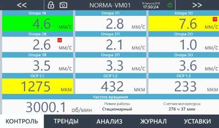
- Measurement of vibration velocity RMS, and the RMS of vibration bearing supports of induced draft fans, draft fans, mine fans and pumps etc.;
- Signaling the transition of the machine in zone C "ALARMS" and D "TRIPS", relay outputs, led indicators;
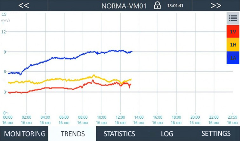
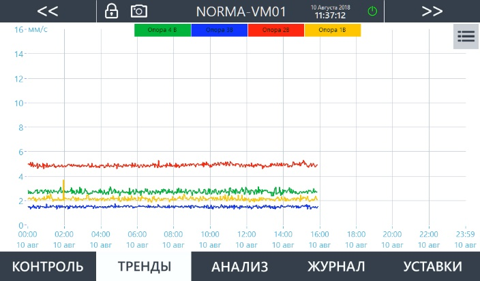
- Visualization of current values and a daily trends options at a computer monitor;
- The formation of the archive of the received data and a log of alarm events and failures of equipment and communication lines;
- Customizing settings for each measured channel;
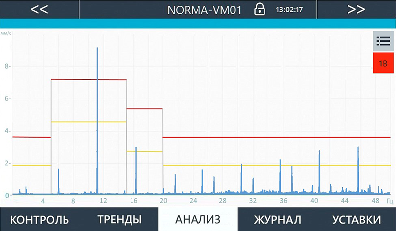
- Setting the reference spectral masks in the factory of the manufacturer at the customer's request;
- Integration with external devices and systems of the enterprise (for example, ACS TP) at the level of field equipment of the line 4...20mA and/or level control devices via Ethernet, Modbus TCP/IP and/or 4...20mA.
-
Specifications
| PARAMETER |
UNIT |
VALUE |
| Frequency range |
Hz |
2(10)…1 000 |
| Frequency filters, f - current frequency |
Hz |
2(10) …1/2 f |
| Measurement range of vibration velocity RMS |
mm/s |
0,1…30,0 |
| The measurement range of RMS vibration |
mkm |
0,15…2000,0 |
| Error of vibration measurement, less than |
% |
5 |
| Temperature sensitivity, less than |
% |
1,5 |
| Measurement range of frequency of rotation |
rpm |
3…45 000 |
| The frequency measurement error, less than |
% |
±0,1 |
| Relay outputs |
|
2 |
| Commutation parameters of relay |
V
V
A
|
=150
~150
2
|
| Interfaces |
|
Ethernet
Modbus TCP/IP(option)
current loop 4…20мА(option) |
| Database |
|
MySQL |
| Power supply |
V
Hz
V
|
~220±10%
50±1%
30; 125
|
IP Rating
electrical cabinet
sensor
|
IP |
54
67
|
Operating temperature
controller
sensor
|
°С |
-20...65
-40…125
|
Dimensions
electrical cabinet
sensor
|
sm
mm |
31х17х28; 54х17х28
35,5х33х21,5
|
SOFTWARE
The software NORMA-VM SW1.0 Exh&Fun provides all the necessary tools for monitoring the technical condition of the unit.
Software
NC-Monitor 2.0 Software Package
Software package for archiving and visualization of any technical and technological parameters, such as general vibration level, mechanical parameters, temperature, pressure
- Several types of display of current parameter values (mimic diagram, table, histograms);
- Color indication of alarming parameter values, markers of inactive events;
- Customizable screen for presenting archived data for a selected period of time;
- Filtering log events;
- Reporting by parameters and events;
- Setting settings individually for each parameter or for groups of parameters;
- Express test mode for equipment and communication lines.
For a local workstation with a 7’’ monitor, the version of the NС-Monitor 1.0 software package is used. This version retains all the functionality of the NC-Monitor 2.0 package (except for the mimic diagram) with adaptation for the touch mini-monitor.
NC-Vibro 2.0 Software Package
Software package for archiving and visualization of technical condition parameters of critical machines for monitoring and vibration diagnostics
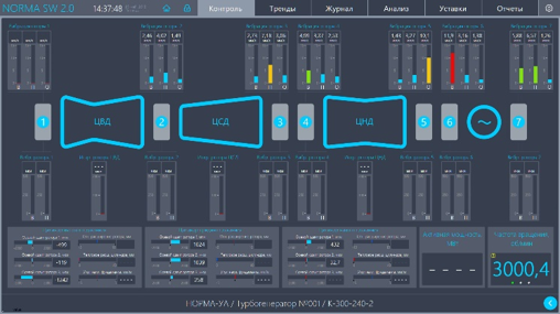
- Inclusion in the software package of up to 12 controlled units;
- Display of current values of vibration parameters and mechanical quantities on the mnemonic diagram of the unit in the form of a bar chart;
- Displaying parameter trends for a selected period of time;
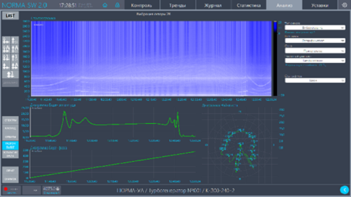
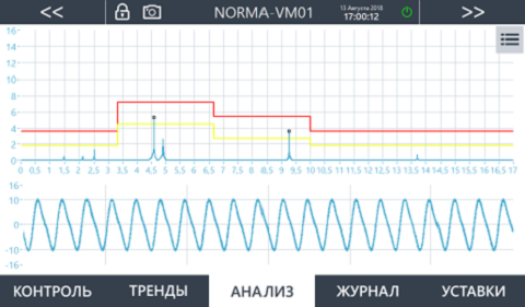
- Spectral analysis (spectrum, cascade, spectrograms), plotting the orbits of the rotor in the bearing bore, the ascent of the shaft, the Bode, Neyquist diagrams;
- Logging of alarm events and equipment malfunctions with a filtering system by channel, by event type and by time;
- Report generation with saving the document in PDF format or printing;
- Change of settings, hysteresis and time delay of relay operation;
- Reconfiguration of control modules and logic modules;
- Emulation mode for testing equipment.
For the local workstation with a 7’’ monitor, the NC-Vibro1.0 version is used, retaining the monitoring functions (except for the mnemonic diagram) and the diagnostic functions in terms of spectral analysis.
div class="uk-grid" data-uk-grid-margin>
NCH system chassis and NCR boxes
NCH chassis
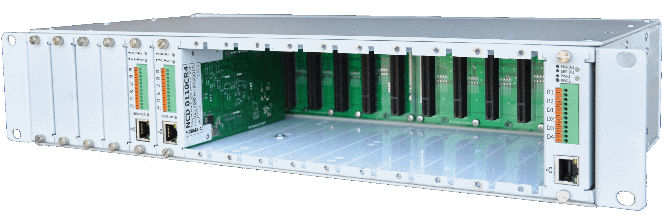
The system chassis (rack) secures and powers control modules, logic modules, and other system modules.
NCH2019 chassis 16 slots, version 2U19 ";
NCH2010 chassis 8 slots, version 2U10";
NCHxxxxP chassis with redundant power supply and ATS module.
The chassis with functional modules installed in it is mounted in an electrical cabinet. Access to all module slots is from the front.
NCR Boxing

Sealed box provides fixation, nutrition and protection IP54 control functional devices (modules).
NCR.S boxing for 6 slots, (WxHxD) 274x222x153;
NCR.M boxing for 12 slots, (WxHxx) 385x222x153;
NCR.In boxing for 16 slots, (WxHxx) 498x222x153.
Boxing consists of an electronic unit and a casing. An electronic unit with modules installed on its cross-board can be easily removed from the housing for maintenance without dismantling the entire structure;
Boxes are mounted on a wall or a metal vertical structure.
NCB control devices
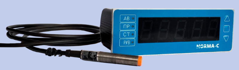
Speed control device NCB0412
The monitoring system of rotational speed of the turbine with built-in hour meter.
FUNCTIONALITY:
- Measurement of the speed of rotation of the turbine in the range 3...45 000rpm;
- Digital display of rotation speed on the tachometer unit and the remote unit display;
- Visualization of the daily trend of the rotation speed on the computer monitor;
- Led indication of exceeding thresholds (warning/alarm);
- The results of the signals of "dry contact" for external devices sound and light alarm and protection devices;
- Accounting of operating time of the unit in different modes (stationary / accel / overrun) – hour meter;
- Customizing settings, the range of steady state and starting values hours;
- Archiving trends speed automatic logging of events and alarms;
- Integration into the APCS via Ethernet.
The composition of the tachometer system includes a tachometer unit NCB 0412, block remote indication NCB 0052 (panel mounting) / 0051 (installation on the unit) and inductive sensor IF5646 ("IFM" Germany). To make settings, and view the archived data used the software package NORMA-RS SW 1.0.
-
SPECIFICATION:
| Parameter
|
Unit
|
Value
|
| Range of measurement1
|
rpm |
3…45 000 |
| Resolution |
rpm |
0,1 |
| Measurement accuracy |
% |
±0,1 |
| Data update rate on the monitor |
s |
2 (on request 0,35…3) |
| Setpoints, hysteresis, time delay |
|
2 (customizable) |
| Relay outputs with events |
|
2 |
| Relay output "fault" (optional) |
|
1 |
| Digital communication interface for remote indication |
|
RS-485 |
| Digital communication interface to external systems |
|
RS 485
Ethernet
Modbus TCP/IP(optional) |
| Device-to-computer communication interface |
|
Ethernet |
| Database on a computer with specialized software |
|
MySQL |
| SD Memory Card (optional) |
Gb |
32 |
| Power supply from single-phase AC |
V
Hz
V DC
|
~220±10%
50±1%
10
|
Ingress Protection Rating
device
transducer |
IP |
54
67
|
Temperature range
device
transducer |
°С |
-20...65
-25…80 |
Dimensions
device
transducer |
mm |
166х77х40
М12х1; L71 |
*1 - The upper limit of the speed range (n) depends on the circumference of the shaft (C) and the label length (l), and calculated by the formula: n=(l x Fn)/60 x C, where Fn is the switching frequency of the sensor