SMS / SAS Seismic Monitoring / Alarm System
Monitoring system and anti-seismic protection for nuclear power plants and other hazardous industrial sites with advanced data processing
OUTLINE
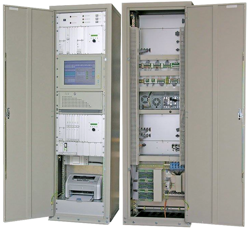
The core of the SMS / SAS is a Central Processing Unit (CPU) with a multi-channel digital recorder system rack mounted in a seismically and EMC safe cabinet together with an industrial PC and relevant peripherals.
Accelerometers, seismometers or complete seismic station packages, which are referred to as Detection / Recording Units (DRU's) are placed at remote locations that are connected to the CPU through shielded or fiber optic cables.
The system has been designed in a way that it is not bound to a single topology. There could be only the sensors or both sensors and data acquisition out in the field. Advantages of these topologies are briefly explained in the specifications section.
The system has a great modularity and flexibility so that an instrumentation upgrade is simplified and that as much as possible existing elements can be reused.
State of the art GeoDAS software is utilized in the CPU.
GeoDAS monitors all DRU's in parallel, as a result of the dedicated serial communication links that are provided by the system hardware.
By monitoring continuously the DRU's, the CPU detects seismic events, generates associated alarms and automatically processes the recorded data.
Also it performs periodical tests on the system and monitors the system-wide state of the health as well as analyses the detailed cause of any malfunction.
The result of the data processing is provided in a report a few minutes after the occurrence of an event.
For each measuring channel the recording threshold and the alarm limit values can be set individually. Detailed response spectrum limits can be fully defined along with other parameters as required by relevant regulations or customized user requirements.
FEATURES
- 1 Recording, advanced analysis and annunciation according to latest or custom regulations
- 2 Automatic RSA, RSV, CAV calculations and OBE, SSE exceedence evaluation
- 3 Up to 48 remote stations or sensors
- 4 18 or 24-bit event based and/or continuous recording
- 5 Common timing and triggering within the system
- 6 Completely over-voltage protected
- 7 Continuous system-wide SOH monitoring
- 8 Полная защита от перенапряжения
- 9 Seismically and EMC proven design
- 10 Comprehensive configuration of the whole system via the enhanced computer interface
SMS / SAS with Centralized Recording
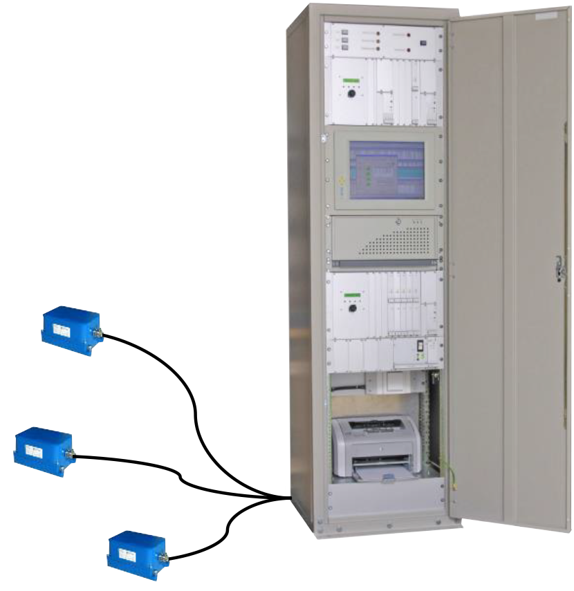
Simple devices in controlled area (analog sensors).
Simplified diagnostics and maintenance.
Higher compatibility with existing systems for upgrade.
SMS / SAS with Decentralized Recording
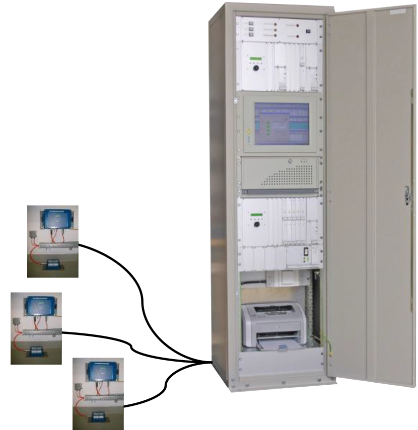
Independent recording units increase redundancy and reliability.
Link from remote to central can use Fiber Optics.
Digital transmission between remote and central locations.
Seismic Switches
Seismic switches in a centralized recording system are implemented as a separate acquisition module with its own power supply. It has independent cable connection to its own accelerometer sensor. Alarm output is generated from the cabinet.
In a de-centralized system, seismic switches are implemented as additional remote unit. Instead of a trigger information, they forward to the central system a signal defined by the alarm level. Seismic switches can be also implemented as fully independent units having directly the alarm output in the form of relay contacts.